Gene Giacomelli

Director of CCEA
Department of Bioresource Engineering
Rutgers University
20 Ag Extension Way
New Brunswick, NJ USA 08901-8500
Gene Giacomelli
Director of CCEA
Department of
Bioresource Engineering
Rutgers University
20 Ag Extension Way
New
Brunswick, NJ USA 08901-8500
ABSTRACT:
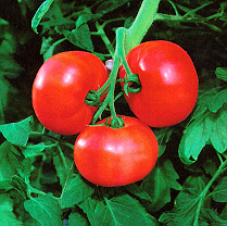
A research/demonstration greenhouse for the production of greenhouse tomatoes
using the single truss tomato production system (STTPS) has been designed and
erected in Florence, New Jersey, at the Burlington County Resource Recovery
Facility. The facility will demonstrate the potential for using methane gas from
landfills or other sources for heating and lighting to maximize crop production
while minimizing energy costs. The main greenhouse is 76.97 meters long with 7
bays at 10.97 m with each bay being 51.81 m long. The headhouse is 14.6 m wide
and 62.2 m long is placed between the main greenhouse area and a 10.97 m wide
and 27.4 m long nursery facility. Tomatoes grown on transportable benches are
moved to the workers for pruning, inspection and harvest. Hives of bees provide
pollination. Supplemental lighting is provided by 430 watt HID (high intensity
discharge) high-pressure sodium lamps. Power will be supplied to the lights by a
430 KW co-generation unit operating on methane gas produced by the adjacent
landfill. Rejected heat from the co-generation engine will be stored in the
floor. A floor heating system and overhead 50 mm hot water steel pipe provide
heating. Ventilation is accomplished through electric fans and a calibrated and
screened inlet ventilation window. Evaporative cooling is also provided by a
high pressure fog system. Currently 3 sections are glazed with glass and 4
sections are glazed with two layers of polyethylene film.
Introduction:
This Burlington County Research and Demonstration Greenhouse research facility is a part of the New Jersey Ecocomplex. The Ecocomplex is the nation's first research, teaching and technology transfer experiment station focusing on environmental issues. The project is funded by the Burlington County Board of Chosen Freeholders with assistance from the New Jersey Economic Development Authority.
The faculty of the Bioresource Engineering Department has been conducting
extensive research over a period of years on greenhouse design, energy
conservation, alternate energy use, unique tomato production systems and
automatic handling of transplants using machine vision and robotics. The design
of the R&D greenhouse discussed here is a synthesis of many of these
research activities into a New Jersey Agricultural Experiment Station Paper #
NJAES P03130-13-96 demonstration unit of modest production size. The size of the
greenhouse research and demonstration facility is limited at this location
because of the terrain which is surrounded by designated wetlands, Figure 1. The concepts
being introduced into the design include, use of methane gas as a primary energy
source, computer models which predict date of first flower based on PAR
(photosynthetically active radiation) energy received, supplemental lighting to
achieve model predictions, floor heating and energy storage systems,
polyethylene film double glazing, the single truss tomato production system,
screening for insect control and the use of thermal screens for cooling and
energy conservation. Ebb and flood hydroponic crop production in conjunction
with transportable benching will be featured in the growing system. Robotic
transplanting and computer vision analysis for seedling selection will also be
demonstrated in an extended research phase. In addition several computer models
have been developed which can be used in the design of a production facility as
described in this paper, including an economic model, a growth model and a
materials handling model.
Materials and Methods
Greenhouse Design
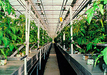
The greenhouse as shown in Figures 2 and 3 is 76.97 meters long with 7 bays, 10.97 meters wide with each bay being 51.81 m long. The headhouse is 14.6 m wide and 62.2 m long and provides areas for an office, storage and work space for sorting, packing, handling and transplanting of the crop. At one end of the headhouse the boiler and the mechanical room are located and electric service entrance equipment. Nearby, the 600 KW co-generation unit will be located on a slab outside the headhouse near the electric panel. Located adjacent to this area are the liquid fertilizer irrigation storage tanks, stainless steel screens and nutrient and water holding tanks for the hydroponic growing system. In addition to the main greenhouse there is a 10.97 m by 27.4 m plant nursery facility for producing the large number of transplants required for STTPS production systems. The nursery area is separated from the main greenhouse growing area to isolate and separate the younger from the older plants in the two areas of production.
The greenhouse design features two glazings. The nursery area and three sections of the greenhouse growing area are glazed with glass and 4 sections glazed with two layers of air-inflated, polyethylene film. The greenhouse manufacturer chosen, features an interchangeable design from glass to polyethylene film. The ridge and furrow design has aluminum gutters which will receive either glass glazing bars or flat or curved aluminum bars to support the polyethylene film. To change the glazing only the support members need to be changed. At any time in the future at modest cost, the greenhouse can be changed to whichever glazing proves to be appropriate for this installation based on data collected, which includes amount of PAR (photosynthetically active radiation) received and the thermal energy required for heating in each section. These differences will be correlated along with crop performance and yields.
The floor of the greenhouse features a floor heating system of 19 mm polybutylene pipe, spaced on 30.5 cm centers. Each pipe loop is 103 m long and is connected to a double return header system as indicated in Figures 4 and 5. The double return header system ensures that each 'slug' of water travels the same distance to and from the boiler and co-generator unit located in the headhouse. Equal distances create equal friction which in turn provides equal flow in each loop without the need for control valves or changes in pipe diameter. The floor of the greenhouse has a very large thermal mass. Waste heat from the co-generator will be captured and stored in the floor as the warm water is circulated throughout the floor heating system. The generator can operate for long periods of time without affecting air temperature in the greenhouse because of the huge energy storage capability of the greenhouse floor. During periods when heat is required the heat stored in the floor will be transmitted to the greenhouse based on the temperature difference between the floor and the aerial environment. Traffic paths are paved in each bay and at the ends of the greenhouse. The rest of the entire floor is of sand construction with an impermeable barrier under the sand to collect all water which escapes from the irrigation system. This design limits unwanted runoff and potential ground water pollution and creates an environmentally neutral greenhouse.
Environmental Control System
The aerial and root environment of the greenhouse is controlled separately by an Argus computer system with sensors mounted in each zone throughout the crop area. Overhead hot water loops of 5 cm pipe, see Figure 4, provide the heating capacity required in cold weather and augments the floor heat heating system. The overhead loop is very responsive and the floor loop has a large response time delay to the control system. Three and four way mixing valves on the hot water system anticipate the needs of the greenhouse and based on outside temperatures control the temperature of the water in the system. As the air temperature approaches the set point the valve position is changed so that more of the water is recirculated and less comes from the boiler. At the time the sensor is satisfied and the pump stops the temperature of the water in the large pipe loop is near the greenhouse set point temperature. This ensures that there will be a minimum overrun of the set point. When a mixing valve is not used the temperature in the overhead pipe loop will be near the boiler temperature when the pump stops. This high temperature water provides a tremendous energy source causing an overrun of the setpoint, particularly in mild weather. The importance of the mixing valve has become more evident as energy conservation and heating efficiency have become important in greenhouse operation. The computer system also controls time of day set points in the several zones within the greenhouse and records temperatures so that the manager can determine the temperature at several locations in the greenhouse at any time of day. Hot water for the overhead system is supplied from a 1176 KW boiler powered by propane or methane biogas from the adjacent landfill.
Overhead thermal screens are used to reduce heat loss at night in the winter and reduce daytime temperatures during the warmer parts of the year. At the control of the computer, the thermal screen is retracted or extended depending upon the need. During the heating period at night the screen will be extended to seal off the attic space from the crop growing area. The use of thermal screens has reduced the energy loss from the greenhouse on average about 30%.
During the cooling mode the thermal screens are operated by the computer based on inside temperature and the amount of PAR radiation entering the greenhouse. Light is critical for optimum plant growth but as leaf temperatures increase photosynthesis is adversely affected. The computer balances the need for PAR with the high leaf temperatures and extends the thermal screen during periods of high light levels if the ventilation system can not keep up with the temperature set points.
Ventilation is accomplished mechanically by exhaust fans coupled to a calibrated window inlet. The design ventilation rate using thermal screens for summer shading is 1.7 cubic meters per square meter at 2.54 mm pressure. Screening is installed on the ventilation inlets as indicated in Figure 7 and performance of the ventilation system with and without the screening is illustrated in Figure 8. The window opening is designed to give the incoming air an apparent velocity of 3.6 meters/sec. This causes minimum static pressure drop on the fans and provides a very high velocity to the incoming air. The jet effect of the air entering the greenhouse through the controlled inlet causes excellent mixing between the greenhouse ambient air and the incoming air, see Figure 6. During periods of cold weather the cold incoming air is thoroughly mixed by this process before it strikes any of the plant material and subcools the growing area near the ventilation inlet. The air in the greenhouse is mixed much like the jet action of a water hose inserted into a barrel causes mixing of the contained solution.
Further temperature control is provided by evaporative cooling during extreme weather. High-pressure fog nozzles are placed over the center walkway in each section and along the ventilation inlet. Water under high pressure is injected into the greenhouse environment at these locations. The very small droplet size provides for rapid evaporation into the greenhouse air with the energy to evaporate the water coming from the greenhouse air. Cooling can occur to the limit of the wet bulb temperature. It is possible during clear days to experience a 6oC degree drop in temperature of the incoming ventilation air at the window and since the nozzles are placed over the walkway in each section, provides cooling throughout the growing area. On more humid days the temperature drop may be reduced only 3oC. When the evaporative fog system is operating, the greenhouse ventilation system operates to provide an air exchange of approximately 25% of a volume change per minute. This rate provides a balance between controlling greenhouse humidity and discharging the fog before it has had time to evaporate and cool the greenhouse ambient air. A ventilation rate which is too high reduces the efficiency of cooling by exhausting cooled air while a ventilation rate which is too low does not lower the humidity in the greenhouse which controls the amount of water vapor being evaporated. The ventilation rate is adjusted by the Argus computer controlled environmental control system.
STTPS System
 The
STTPS (single truss tomato production system) has been developed to mechanize
tomato production in greenhouses. Conventional greenhouse production provides a
spacing of 2.5 plants sq meter. This space is required to provide for
maintaining and harvesting the crop. In the STTPS, tomatoes are grown on
transportable benches at a nominal density of 10 plants per square meter, four
times the normal density because no access aisles are required for workers to
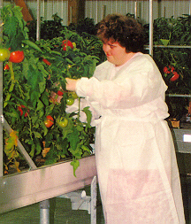
care for the crop. Tomato plants are planted on transportable benches, pruned
above the first flowers and moved to the workers for the required operations,
including pruning and harvest. Pollination is provided by hives of bees spaced
throughout the growing area.
The
STTPS (single truss tomato production system) has been developed to mechanize
tomato production in greenhouses. Conventional greenhouse production provides a
spacing of 2.5 plants sq meter. This space is required to provide for
maintaining and harvesting the crop. In the STTPS, tomatoes are grown on
transportable benches at a nominal density of 10 plants per square meter, four
times the normal density because no access aisles are required for workers to
care for the crop. Tomato plants are planted on transportable benches, pruned
above the first flowers and moved to the workers for the required operations,
including pruning and harvest. Pollination is provided by hives of bees spaced
throughout the growing area.
The transportable benches used in this system are 4.9 m long and 1.4 m wide. Two are placed across the 10.9 m bay leaving a 46 cm access and management aisle between them and allowing for a small clearance between the end of the benches and the greenhouse supporting posts, see Figure 4. There are 68 benches per zone which move on bearings and rollers on two rails which provide support beneath them. Special equipment allows the benches to index with a conveyor in the aisles on each side of the greenhouse for transport to the headhouse. With a 16 by 4 plant spacing, there are 64 plants per bench or 9.3 plants per square meter.
 Several
options are available for moving the single truss tomatoes throughout the
greenhouse. These include moving the benches in a loop within the greenhouse bay
and having the workers stationed at either end of the bay. As the benches reach
the end of the greenhouse bay the workers prune, examine or harvest depending
upon the need. The workers perform tasks on one half of the bench in one aisle
at the end of the greenhouse and on the other half of the bench in the other
aisle at the other end, see Figure 9. Another option
is to move the benches on the conveying system to the headhouse where the bench
configuration allows for workers to operate on both sides of the bench. Normally
the benches are moved to the headhouse following the final harvest. At that
point the remaining vegetative material is removed and taken to a compost site
at the Resource Recovery facility. The empty benches are cleaned and replanted
with transplants brought to the work area from the 10.97 by 27.4 nursery
greenhouse. The completed benches are then moved back to the appropriate growing
area in the greenhouse. Currently these and other options are being pursued
during the early stages of operation.
Several
options are available for moving the single truss tomatoes throughout the
greenhouse. These include moving the benches in a loop within the greenhouse bay
and having the workers stationed at either end of the bay. As the benches reach
the end of the greenhouse bay the workers prune, examine or harvest depending
upon the need. The workers perform tasks on one half of the bench in one aisle
at the end of the greenhouse and on the other half of the bench in the other
aisle at the other end, see Figure 9. Another option
is to move the benches on the conveying system to the headhouse where the bench
configuration allows for workers to operate on both sides of the bench. Normally
the benches are moved to the headhouse following the final harvest. At that
point the remaining vegetative material is removed and taken to a compost site
at the Resource Recovery facility. The empty benches are cleaned and replanted
with transplants brought to the work area from the 10.97 by 27.4 nursery
greenhouse. The completed benches are then moved back to the appropriate growing
area in the greenhouse. Currently these and other options are being pursued
during the early stages of operation.
Supplemental Lighting
Low winter light levels limit tomato production in our latitude. Supplemental lighting is required to maintain uniform year-round production demanded by marketing systems located in areas of high population density like New Jersey. Supplemental lighting is provided by 430 watt high pressure sodium fixtures capable of delivering PAR lighting as required throughout the year. Six lamp fixtures are spaced at 1.83 meters across the bay and and there are 18 lamps spaced at 2.54 meters along the bay. The total of 108 lamps per bay gives a spacing of 4.65 square meters per lamp and radiation of 92 watts per square meter, see Figure 10.
The energy for the HPS lamps will be supplied from the power grid or from the co-generation unit powered by the biogas from the landfill. This type of load, used on off-peak hours is very beneficial for power companies with daytime peaking energy consumption.
One of the advantages of the STTPS is that the canopy is horizontal and lends
itself to supplemental lighting. Early experiments (McAvoy, 1984, McAvoy et al. 1988 & 1989) led quickly to the conclusion that in supplemental lighting of tomatoes there were advantages, relative to traditional growing, to working with a plant terminated after the first fruit truss develops. Supplemental light is most effectively utilized if a horizontal plane can quickly be filled with foliage (high LAI, leaf area index) with all the active foliage at a uniform distance from the light source to provide a uniform intensity. In a multicluster plant the weight per cluster is variable and in later stages of growth insect infestations, disease and mechanical injury problems increase with time to potentially reduce production.
Giniger et.al., (1988) found that light received during the seedling stage from emergence to flowering was always strongly correlated with the time to first anthesis. An equation was developed to predict flowering based on the PAR received by the seedling. On the other hand, light received during the period from flowering to harvest was strongly correlated with the total amount of fruit. Another equation was developed for the production stage which predicted yield based on PAR received. These two linear equations are used in a growth model.
Management of Supplemental Lighting
Natural and supplemental light is monitored by the Argus system so that the total PAR can be held constant for each crop throughout the year. The required amount is provided by the HPS lamps by varying the length of operation throughout the day. At one extreme the targeted amount of light is provided almost completely from May to September in New Jersey. At the other extreme during the darker and shorter daylength period supplemental light is required to maintain a constant schedule. In each crop the actual light is monitored on a continuous basis and the input of supplemental light adjusted throughout the period to achieve the desired total by the end of the vegetative stage. Current modeling and case studies indicate that a feasible strategy involves a combination of daily total monitoring in combination with expected historical averages for the period.
Results
The research/demonstration greenhouse was dedicated on April 9, 1996 by New Jersey Governor, Christine Whitman. The program featured an address by Dr. Merle Jensen on the future of CCEA. The first tomato crop has been harvested with production averaging .9 kilograms per plant. The STTPS system allows the cropping schedule to be repeated 5 times throughout the year. It is anticipated that succeeding crops will equal or surpass this yield. To date, no chemical applications for disease and insect control have been used. The ventilation inlet screening may account for some of this. PAR readings are being taken comparing the two glazing sections and energy measurements are being made on each section as well. The materials handling system is working well. All of the environmental control systems including floor heating, overhead heating and ventilation and evaporative cooling have performed to date as expected. Labor is being provided by 6 people from the Burlington County's Occupational Training Center. These workers are seeding, transplanting, pruning and harvesting the crop.
The screening illustrated in Figure 7 has performed well and is designed to exclude white fly and larger insects. Figure 8 indicates that the system is operating safely below the the design static pressure limit of 2.54 mm. When the pressure increases about this level the screening will be cleaned. Previous experience in an experimental greenhouse indicated that no cleaning was necessary the first year.
Summary
A series of coordinated research projects were completed to create the knowledge base necessary for the design and management of the single-truss tomato production system being used in this greenhouse facility. They include:
* biogas utilization
* effects of HPS lighting on tomato plant growth
* development of a plant factory model
* computer simulation and validation of the cropping system
* screening seedling to improve uniformity
* design of transport and elevation system
* tomato production in rockwool on ebb-flood benches
* comparison of labor standards
This facility, using methane gas from the landfill for co-generation for the energy required for supplemental lighting and the ventilation system and the substitution of methane for natural gas for the production of hot water used in the heating system provides a great opportunity to learn more about the system on a larger scale. Studies at this research/demonstration facility will detemine if the STTPS has great potential for the production of high quality tomatoes for the large New York City and Philadelphia metropolitan markets.
References
| CCEA Home | Send Email |